

Polygon turning
A polygon cutter is a driven disc with evenly spaced blades that spins beside the turning part, geared to it: the same direction, exactly twice as fast. Each blade cuts two opposite flats every turn of the part, so three blades cut a hex and two a square. We run it on a dedicated polygon turning machine, so hex heads and nuts get every flat at once, without a milling operation.

Lock on, feed in, stop at size.
- STEP 01
Load the blank
The nut arrives round: already turned to the hex's size across the corners, which will be this turned surface (1.796 to 1.876 in. for a 1 in. heavy hex nut, ASME B18.2.2), and already threaded. It is screwed onto a threaded arbor in the polygon machine's chuck.
- STEP 02
Gear the cutter to the chuck
The polygon cutter, a driven disc with evenly spaced blades, sits beside the part on a parallel axis. Gears and a drive shaft tie its spindle to the chuck: the same direction, exactly twice as fast.
- STEP 03
Feed in
The cutter feeds in toward the turning part. Each blade passes through the bar twice for every turn of the part and cuts two opposite flats, so three blades cut all six flats of a hex together.
- STEP 04
Stop at size
The infeed stops at the across-flats size: 1.575 to 1.625 in. on a 1 in. heavy hex nut. The same cutter makes a larger or smaller hex by stopping at a different depth.
- STEP 05
Unload
The finished nut is spun off the arbor and the next round nut threaded on. The machine cuts only the flats; the nut is turned, drilled and threaded before it comes here.
- Flats with a flatness tolerance, a single flat, or flats of different sizes are milled: a polygon cutter leaves a shallow curve and always cuts equal, opposite pairs.
- Standard heads made in quantity are hot forged. A forged head is gathered from bar the size of the shank; a head machined from bar needs bar as big as the head across its corners, as ASTM A193 notes.
- Hex sockets are inside the part: they are broached, not polygon turned.
Every flat at once.
Bolt heads and other hexes were traditionally milled one face at a time, which is slow and costly. A geared polygon cutter cuts every flat while the part keeps turning, so all six flats are cut together in one clamping and come out equal.
The flats are very slightly crowned rather than dead flat, because each blade follows an ellipse, not a straight line; a bigger cutter flattens the curve. A wrench does not notice it. Where a drawing puts a flatness tolerance on the flats, they are milled.
A nut made this way is machined from bar, so an ASTM A194 2H nut is marked 2HB, and like every 2H nut it is quenched and tempered after it is made, by an outside Houston heat treater. 2HM and 7M nuts also get a final stress relief after all machining.
Parts and features.
Polygon turning: common questions.
Why exactly twice the spindle speed?
At 2:1, turning the same way, each blade's path round the part is an ellipse centred on the part's axis and fixed on it, so every pass recuts the same two opposite flats. Off that ratio the flats would not stay in place.
Are polygon-turned flats truly flat?
Very nearly. Each face is part of an ellipse, so it is slightly crowned, and a larger cutter makes it flatter. That suits a wrench. Where a drawing sets a flatness tolerance on the flats, they are milled.
What size bar does a hex need?
At least the hex's width across corners, because the corners are the bar's own turned surface. A 1 in. heavy hex nut is 1.575 to 1.625 in. across the flats and 1.796 to 1.876 in. across the corners (ASME B18.2.2), so it is cut from bar of at least 1.796 in.
Polygon turning or forging?
Forging gathers a head from bar the size of the shank, saving material on standard heads made in quantity, and its grain follows the head. Polygon turning needs no dies made for one size, so it suits special sizes and short runs.
Before and after it.
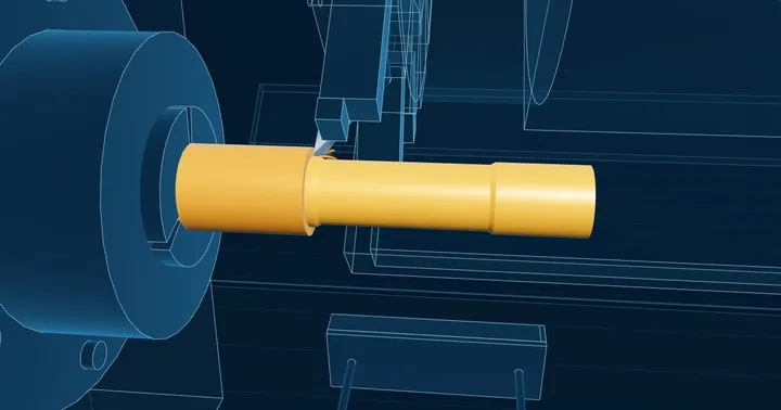
CNC turning
Studs, collars, nuts and parts from bar
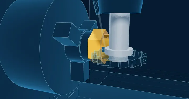
CNC milling
Wrench flats, slots, hexes and cross-holes
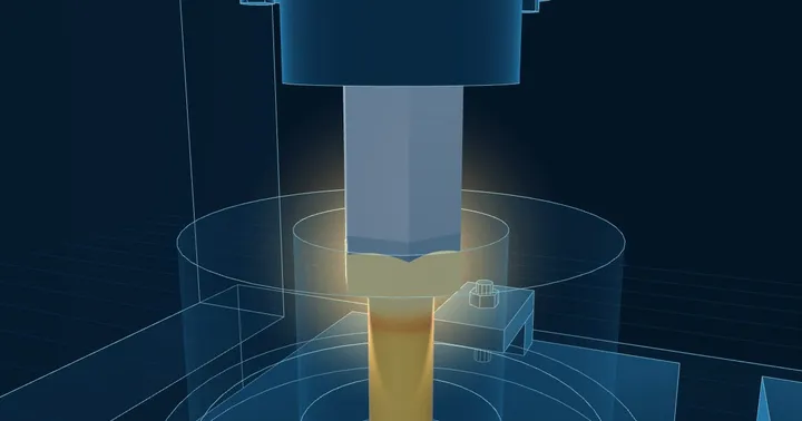
Hot forging
Bolt heads and heavy hex nuts formed from red-hot bar
Thread gauging and dimensional inspection
Threads are checked with Go and No-Go ring and plug gauges, and pitch diameter is measured by the three-wire method or on a thread comparator. Heads, flats, lengths and radii are measured with calibrated instruments and, for complex parts, on the CMM.